
If you have an interview coming up, we have the Top 30 GD&T Interview Questions for Mechanical Engineers for you.
In Mechanical Engineering Interviews, you will need to demonstrate your skillset and knowledge in GD&T, especially for design and manufacturing positions. Structural Engineering positions such as stress analysis will also require the understanding of GD&T principles.
Along with knowing how to answer GD&T interview questions in an interview, the following GD&T interview questions are generally good to know as an engineer.
Check out: Mechanical Engineering Mock Interview where we’ll cover extensive GD&T interview questions for you
What is GD&T?
GD&T stands for Geometric Dimensioning and Tolerancing
GD&T defines a set of standards and principles both designers and manufactures use to create produceable parts.
Why is GD&T Important?
GD&T is important because in reality, parts do not come out perfect.
When parts are being designed, it’s very easy to assume that the numbers we put will be how it comes out to be.
However, this is false as in reality, we deal with error.
We deal with human error, machine error, and circumstances that we cannot control.
GD&T helps bridge the gap between the error and variance by defining what we can and can’t get away with.
When do we use GD&T?
We use GD&T when we are designing parts for a manufacturer to produce.
We will use GD&T symbols to denote a range of tolerances that we can get away with in regards to the design of a part.
In most applications, parts do not need to be theoretically perfect, they just need to be close enough to fit.
GD&T is used to define the relationship between interfaces such as interfacing surfaces or close clearance surfaces.
Specific Examples are:
- Pressure vessesls
- Clearance shafts/bearings
- Coupling hubs
- Welded surfaces
- Structure/Building Feet
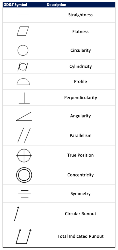
What do the following GD&T symbols represent?
What is flatness?
Flatness defines how flat a surface can be.
It is important to define flatness because for certain applications, we need a flat surface to be level or to have maximum contact area.
Flatness is typically called out on components such as plates, flanges, pedestals, feet, and anything that contacts the ground or has an interfacing surface.
What is parallelism?
Parallelism defines how parallel a surface is relative to another surface.
Parallelism requires referencing a primary datum, and that respective datum will likely have a flatness requirement on it.
See the example of a parallelism call out applied:
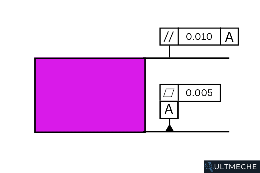
We apply the flatness call out on Datum A of the surface.
Then we apply the parallelism tolerance of 0.010 on the surface that is parallel to datum A.
What is perpendicularity?
Perpendicularity defines how perpendicular a surface is relative to a datum.
It’s important for parts such as gage blocks to be perfectly perpendicular as they are used to measure critical applications or establish perfect datums in machining.
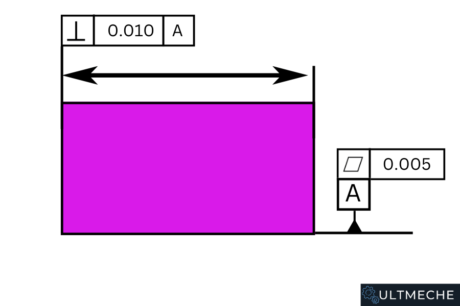
Depending on the application of the part, we would want the surface to be perpendicular with respect to Datum A to be controlled.
Adding a perpendicularity call out will tell the machinist the requirement.
What is straightness?
Straightness defines how straight a surface is relative to the established datum axis.
It is impossible for a surface to be perfectly straight, so as a result, we need to control what the straightness on a respective surface is.
Controlling the straightness of a surface will allow the part to become suitable for the intended design purpose.
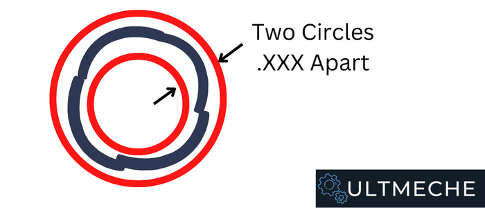
What is roundness?
Roundness defines how round a surface can be.
Roundness will take 2 concentric circles of a circular surface by the called out value and verify that the surface of the part is within those 2 circles.
It is important to define rounds on components because in the industry we ended up with “egg-shaped” conditions in round parts.
When a part has an egg-shaped condition, it will have a difficult time fitting in it’s respective mating surface.
What is cylindricity?
The cylindricity of a part defines both how round and straight a part is along its axis.
You are checking to see how cylindrical the surfaces are with respect to the established datum.
What is concentricity?
Concentricity defines the distance between the center of two different circular surfaces.
Simply put, concentricity defines how circular two holes are relative to each other.
A non-concentric condition between two surfaces would create an “egg-shape”, making it difficult for two parts to fit.
What is Total Indicated Runout?
Total Indicated Runout defines the difference between the maximum and minimum value of a surface when you run a dial indicator along it.
It is very important to control total indicated runout between two tightly clearances surfaces to ensure that they will run as needed.
Along with how circular an object is, it is important to ensure that the part is circular along it’s axis.
This is where Total Indicated Runout comes in.
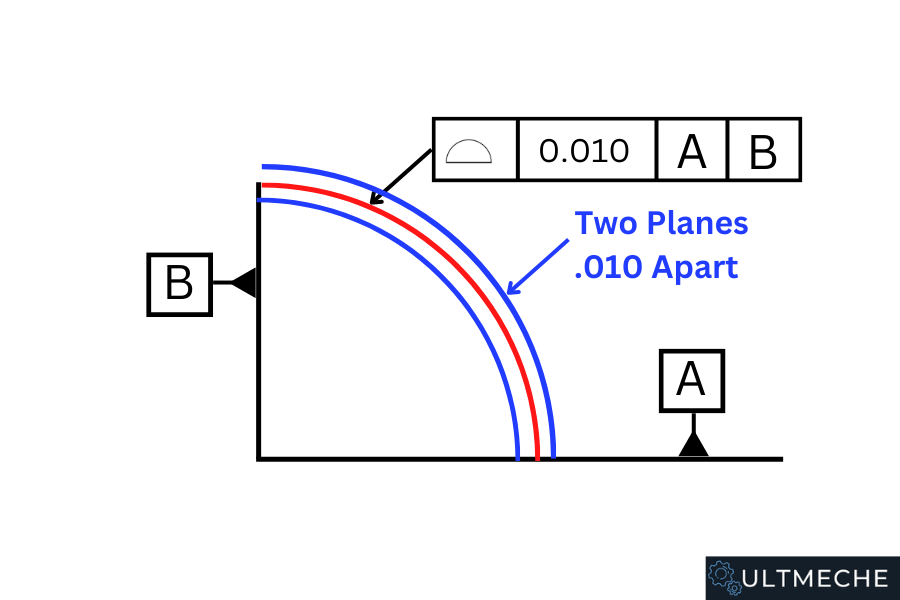
What is profile?
The profile of a surface defines the respective tolerance zone of the surface.
Profile is usually applied on more complex surfaces such as curves or non-standard shapes.
What is a basic dimension?
A basic dimension is a theoretical perfect dimension.
Because it is defined as a theoretically perfect dimension, it is required to add tolerances on basic dimensions.
Basic dimensions are represented with a box around the dimension.
An example of applying a basic dimension would be applying a true position tolerance to holes using basic dimensions, referencing an ordinate dimension.
The basic dimension in this case defines the theoretical perfect dimension from the ordinate dimension to the axis of the hole.
True position in this case would define the maximum distance the axis of the hole can be away from the theoretical perfect location.
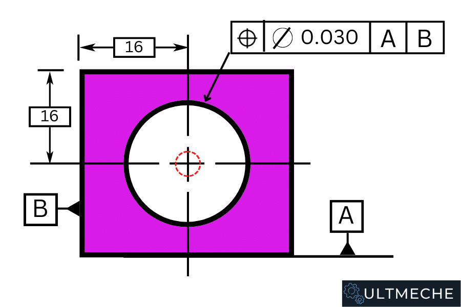
What is true position?
As shown above, true position indicates the maximum value in which a feature can be away from it’s theoretical perfect location.
In the above example, as long as the center of the circle falls anywhere within a 0.030 diameter, the part will be within tolerance.
Why would we want to control the runout on a part?
It is important to control runout so that we can control critical clearances such as shafts, impellers, and wear rings running against each other.
In application such as rotating machinery, it is important to tolerance these components such that we have adequate clearances for our application.
Why would we want to control the flatness of a surface?
It is important to control the flatness of a surface so that interfacing surfaces will lay flat along each other.
This will ensure that parts are aligned, level, and that we have maximum contact surface between two interfacing components.
Along with fit, the engineering function of interfacing components will be reliant depending on how flat surfaces are.
If we don’t have a flat surface, we would essentially be dealing with a surface in which we have many gaps.
This will lower our contact area and could negatively affect mechanical parts.
Why would we want to control the perpendicularity of a welded assembly?
Ensuring a wall is perpendicular to a welded surface is critical.
If a welded piece was not perpendicular, this would cause mis-alignment between parallel features off of the perpendicular wall.
Structures such as buildings or components such as pressure vessels will need gd&t tolerances such as perpendicularity controlled.
What is LMC?
LMC is least material condition.
Least material condition defines a condition in which a part is experiencing the least amount of material available with respect to the feature.
Least material condition to a part corresponding a hole would mean that the hole machined would be the largest. As a result of machining the largest hole size, you would end up with the least material.
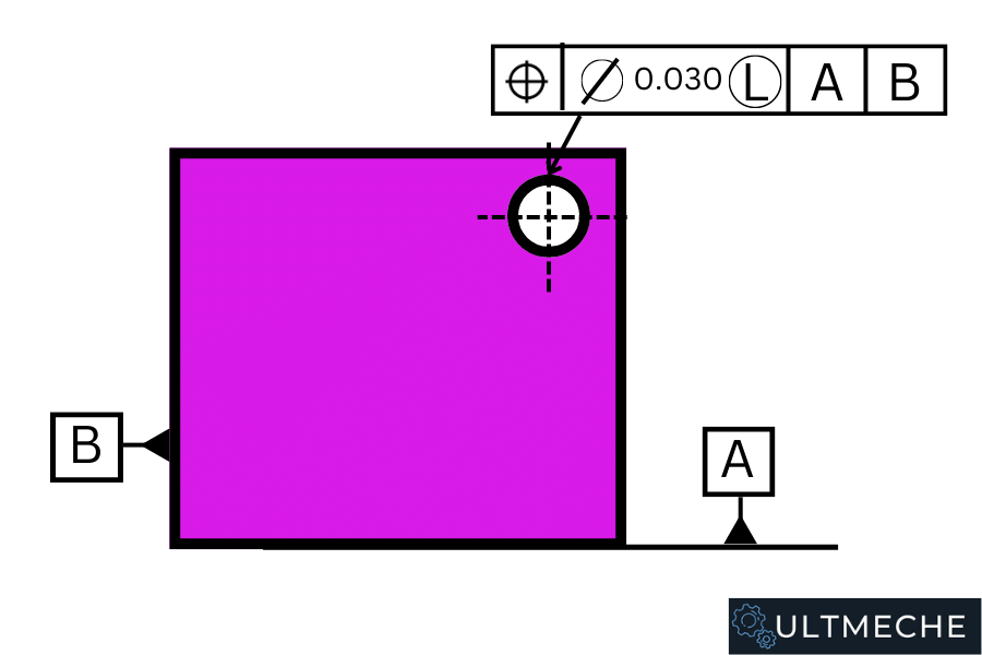
An example of calling out LMC would be for a thin walled condition.
The example above shows that the true position of the feature can differ by 0.030 at least material condition.
A thin walled condition would cause a weaker part at that joint and could cause failure.
What is MMC?
MMC is maximum material condition.
Maximum material condition defines a tolerance applied to a feature in which we would have the maximum amount of material available.
A few examples of maximum material conditions being applied can be represented by internal or external components.
For internal features such as holes, maximum material condition represents the smallest hole size.
For external features such as pins, maximum material condition represents the largest pin size.
MMC can be utilized to ensure two parts never interfere with each other.
What applications would we use tightly toleranced parts?
Applications that utilize tightly tolerances parts include those of:
- Aircraft
- Spacecraft
- Close running shafts
- Couplings
- Critical Flanges
- Gauges
- Measuring Tools
The above need tightly toleranced parts due to the nature of their work.
With very critical applications such as aircraft or spacecraft, it’s important to have very tightly toleranced parts and that suppliers are able to meet those tolerances. In some cases, this could even mean life or death in critical failure conditions.
What applications would be use loosely toleranced parts?
Applications that are able to get away with looser tolerances include:
- Tooling fixtures
- Oil & Gas Components
- Holes for non-critical fasteners
- Lifting Tools
- Non-engineering features on parts
- Adapter Plates
What is tolerance stack up analysis?
Tolerance stack up analysis is a study that determines whether a mechanical system will fit or not given all of the variances in geometry.
Tolerance stack up analysis can be a very heavily arithmetic operation depending on the amount of stack up we have in an assembly.
Stack up refers to the amount of variance we have in a component.
When we put assemblies together, the amount of variance adds up, which drives the need to do a tolerance stack up analysis.
A mechanical example of doing a tolerance stack up analysis would be that of a determining the keyway locations for a multiple stage impeller in an oil and gas application. If we have multiple keyways, the position at which the impeller will sit on the shaft will be subject to variance that adds up. If tolerance stack up analysis is neglected, the parts would potentially not go together.
Have you ever done a tolerance stack up analysis?
Be prepared to talk about a situation where you have used tolerance stack up analysis.
Use the STAR framework in this answer.
Given certain manufacturing defects, how would you disposition this part?
Expect gd&t interview questions in which you will be presented a non-conformance on an object.
Your interviewer will tell you the application of the component, the dimensions of what they were supposed to be, and what the part actually came out to be.
You find that the part is non-conforming to it’s specifications.
You need to be able to verbally answer how you would disposition the non-conformance in a material board review setting.
(Hint – for this type of question, even if you don’t know how to answer it, you want to verbally explain each step of your thought process. In cases like these the interviewer wants to know how you rationalize and do decision making on the spot)
What GD&T standards are you familiar with?
ASME Y14.5 is the standard that engineers use to practice GD&T for manufacturing components.
What tools are used to measure GD&T callouts?
- Pins
- Indicators
- Alignment Rods
- Levels
- Straightedges
- Plumb-bobs
- Laser Trackers
- FARO Arms
- Inclinometers
What is a more economical option – loosely toleranced parts or tightly toleranced parts?
Generally speaking, using loosely toleranced parts are the more economical option.
Loosely toleranced parts are more easy to machine and as a result, are cheaper than tightly toleranced parts.
Sometimes we can’t get away with loosely toleranced parts in the industry and we will need to go with tightly toleranced parts to ensure fit, form, and function.
What are some good practices to implement regarding GD&T in Mechanical Engineering?
- Using standard dimensions
- Use standard drawings with tolerances defined in companies
- Invest in good GD&T training for engineers
Tell me about a time you used GD&T to complete and verify a mechanical design.
For these type of GD&T interview questions, be prepared to talk about how you have implemented GD&T to ensure a system had adequate fit, form, and function.
You will need to use the STAR format – situation, task, action, and result for your answer.
Use keywords such as specific GD&T features, machining methodologies and principles, and a result.
The result portion of your answer should detail how you’ve contributed in achieving some budget or revenue goal.
GD&T Interview Questions – Mock Interview
If you thought the GD&T interview questions were overwhelming check our mock interviewing service out.
We will cover behavioral and technical questions that mechanical engineers will need to know.
The frameworks we present have gotten hundreds of engineers high paying jobs and have allowed them to breeze through their interviews.
We cover GD&T interview questions extensively.
You will have a chance to practice the above questions in an interview setting, which is highly important.
About the author

Kazuyoshi Fujimoto, PE
Founder | Engineering Career Coach | Principal Mechanical Engineer
Kazu oversees all of ultmeche’s engineering services. He provides consulting such as resume reviews, rewrites, mock interviews, and all services career related. Additionally, Kazu performs consulting work regarding Oil & Gas, Automotive, and Aerospace & Defense. Kazu is licensed as a professional engineer in the state of California and has 9+ years of experience in Oil & Gas, Automotive, and Aerospace & Defense.
1 thought on “30 GD&T Interview Questions for Mechanical Engineers”