This comprehensive list gives you 60 Mechanical Engineer Interview Questions and Answers you need to know.
Whether you’re an entry level ,mid level, senior level mechanical engineer, you’ll find all of these questions useful.
Bookmark these Mechanical Engineer Interview Questions and Answers to assist with your job search.
February 29, 2024
These Mechanical Engineer Interview Questions and Answers contain:
- Behavioral Mechanical Engineering Interview Questions and Answers
- Technical Mechanical Engineering Interview Questions and Answers
- GD&T Questions and Answers
- Strength of Material Questions and Answers
- Thermodynamics Questions and Answers
- Design and Process Question and Answers
You won’t find a comprehensive guide like this anywhere else.
These answers contain questions that have been asked in real mechanical engineering interviews by engineering managers.
In the industry we recommend a basic understanding of the engineering courses you took such as Weeks 1~3 Lecture material. (You’ll see as you read on)
If you need some help to prepare for your engineering interview, check out: Engineering Mock Interview
Tell me about your mechanical engineering career.
My mechanical engineering career began as a product design engineer responsible for designing vertical turbine pumps for applications such as oil and gas, power plants, and refineries.
I then transitioned into Manufacturing Engineering in the Aerospace Industry and then shortly transitioned into Mechanical Test Engineering for military aircraft components.
Why did you choose a career in mechanical engineering?
I chose mechanical engineering because I was very interested in math and science and have always wanted to utilize both of those principles in my day to day career.
To this date, I have designed many mechanical systems such as power plants, turbines, refineries, aircraft and they utilize many principles I have learned in school such as thermodynamics, fluid mechanics, and mechanics of materials.
What do you like about mechanical engineering?
I love the challenging aspect of designing components to fit consumer needs.
I truly get a sense of accomplishment when I finish my day to day tasks as a mechanical engineer.
What do you dislike about mechanical engineering?
I dislike the processes and procedures that are associated with mechanical engineering as a whole. As mechanical engineers, we are responsible for the design and integrity of many critical systems. With great power, comes great responsibility.
I understand that the requirement for processes and procedures are necessary to maintain quality of mechanical systems, but it becomes a bottleneck to sustain.
As a result of how difficult it is to work with processes and procedures, I have learned to integrate both in my day to day tasks to successfully design many running mechanical systems to date.
What would you change regarding mechanical engineering?
I would streamline processes wherever possible.
If I had all of the time and resources, I would allocate a huge chunk to streamlining processes and making everything more efficienct.
There’s too many meetings, too many back and forth, and alot of small mistakes end up imploding into something big.
I want to get rid of this and a specific example I have is X.
(Then answer using the STAR format – Situation, Task, Action, Result)
What is your long term outlook on mechanical engineering?
My long term outlook on mechanical engineering is very positive.
Both individual consumers and business use day to day products which heavily rely on mechanical engineers to design and produce.
There will be plenty of opportunities for mechanical engineers to do design work in the future.
Although there will be a ton of work, there will not be as many opportunities for innovation such as what the tech industry is currently experiencing.
What are your favorite skillsets you have regarding mechanical engineering?
My favorite skillsets regarding mechanical engineering are CAD, FEA, and Programming.
I love the challenges associated using each of those skillsets and have created many mechanical systems such as pumps, compressors, turbines, aircraft, spacecraft, and more.
These mechanical systems currently support many products in applications such as aerospace, defense, agricultural, mining, pulp and paper, and oil and gas.
Can you tell me about a time you’ve solved a mechanical engineering problem?
Upon my most recent role as a mechanical engineer, I was responsible for taking over the design of qualification testing.
Some of the individual tasks I had to do were:
- Be responsible for the mechanical integrity of testing components
- Point of contact for all engineering inquiries
- Carry out mechanical qualification testing
Challenges associated with this were navigating issues such as design constraints and lack of resources.
I carried out each of my responsibilities as I needed to, called the right people, set up meetings, etc. and successfully accomplished what I needed to do.
As a result, the application can run safely based on the data that we have tried and tested real time.
Can you tell me about a time you’ve led other mechanical engineers?
After achieving the mechanical test that I had performed (see previous answer), I now know what it took to qualify a part from start to finish. This experience is extremely valuable to the company I was in, and as a result of that, I became the mechanical engineering lead for XXX component.
I was then responsible for delegating other tasks such as creating drawings, documentation, processes, and procedures for other tests and more so directing as opposed to doing the individual engineering work myself.
What defines a force?
Simply put, a force is a push or a pull.
A more complex definition would be a mechanical influence that causes a change on an object.
The change being motion, stresses, acceleration, etc.
Tell me about Newton’s Laws.
Newton’s 1st Law
An object at rest remains at rest unless an external force has acted upon the object.
Newton’s 2nd Law
F = ma
Force equals mass times acceleration.
Through this law, we can predict and solve complex variables in complex mechanical systems that tell us what specific design parameters to include in a system.
Newton’s 3rd Law
For every action, there is an equal and opposite reaction.
A few examples would be:
If you were to push on a wall, the wall would exhibit a force back. (A normal force)
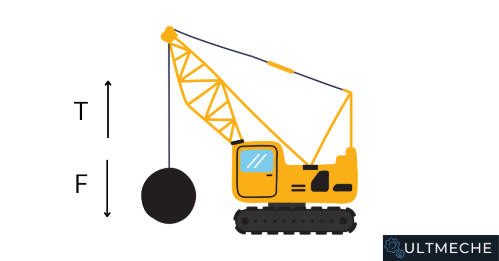
If you were to hang a weight on a rope, there would be an equal and opposite reaction force applied as a tension.
What is friction?
Friction defines the resistance that surfaces experience when they move amongst each other.
What is torque?
A torque is a rotational force exhibited on an object that can be calculated by the cross product of the tangential force and the radius of which the force is applied.
Examples of components that undergo torque are shafts, beams, and fasteners.
What is a moment?
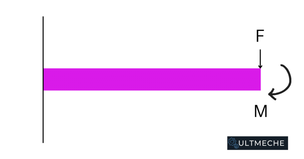
A moment defines the tendency of an object to rotate about a specific point or axis when subject to a load.
A practical example of an object that experiences a moment is a cantilevered beam.
What is a normal stress?
Normal Stress
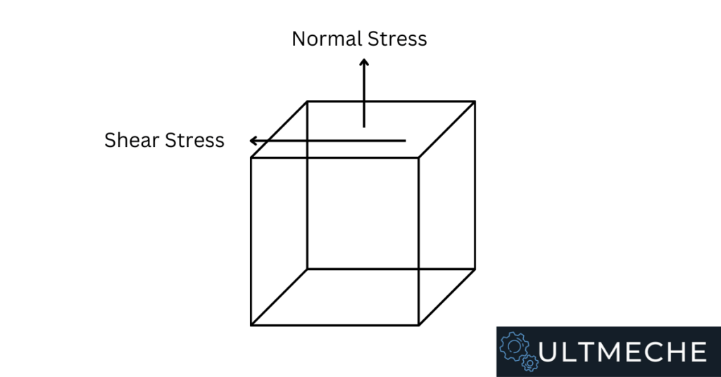
A normal stress occurs when a force is subject to a component perpendicular to the surface. (I.e perpendicular and normal being interchangeable in this case)
What is shear stress?
Shear Stress
A shear stress occurs when there is a force subject on an object that causes deformation along a plane essentially parallel to the surface.
What is the difference between a normal stress and a shear stress?
The difference between a normal stress and a shear stress is the planar or axial direction the stress is experienced.
See figure below for reference.
What is tension?
A tension force is the pulling force that is exhibited by the rope or string upon holding of a mass.
What is stress in mechanical engineering?
Stress in mechanical engineering defines a physical quantity regarding a force over an area.
There are many different forms of stresses such as:
- Tensile stresses
- Compressive stresses
- Normal stresses
- Bending stresses
- Shear Stresses
Mechanical engineers need to account for stress when designing parts. The integrity of the parts they design depend on engineers verifying part capability under stresses.
What is strain in mechanical engineering?
Strain is a dimensionless parameter that defines deformation over the total length of an object.
Strain is a value we measure through applying a load in which a part will experience deflection.
Knowing what the strain a part is undergoing is critical as we can determine important material properties and characteristics upon them.
What is Young’s modulus?
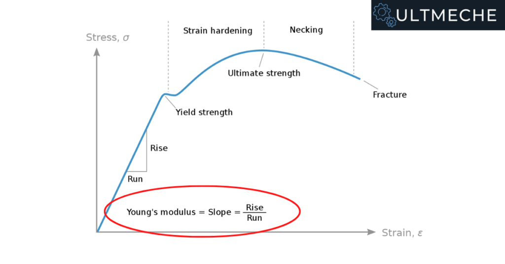
Mathematically, Young’s modulus is stress divided by strain.
Young’s modulus tells us the tendency of a material to withstand changes in length under tension or compression.
Let’s look at a tensile testing example. If we look at the stress, strain curve, we see that after a part begins to yield, the part begins to plastically deform.
What is fatigue in mechanical engineering?
Fatigue in mechanical engineering defines a failure phenomenon when an object is subject to repeating stresses in cycles.
For example, let’s use the rotation of a shaft and an impeller.
The shaft is going to exhibit both torsional stresses and bending stresses from the weight of the impeller and it’s other mechanical components.
Due to cyclic loading, fatigue can cause a crack in a mechanical system propagate and experience catastrophic failure.
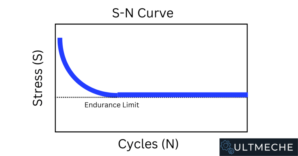
What is endurance limit in mechanical engineering?
The endurance limit of an object in mechanical engineering is defined as the range of cyclic stresses in which an object will experience not crack growth and a theoretical infinite life.
What is stress concentration?
Stress concentration represents a location in a component that is subject to higher stresses.
Stress concentration is important to understand because with different types of geometries, we need to apply certain stress concentration factors to get a more accurate representation of the stresses a part is subject to.
Draw a free body diagram of this mechanical system.
Be prepared to draw free-body diagrams of mechanical systems.
You should just review simple free-body diagrams, don’t go over anything too complex.
Review the basic free-body diagram examples in your Statics and Dynamics courses and you should be good to go.
Key forces to understand in a free-body diagram are:
- Force
- Weight
- Normal Force
- Friction
- Tension
If you can evaluate a mechanical system and understand how those 5 forces act, you will be good to go.
What is your favorite CAD software?
My favorite CAD software so far has been Creo.
Creo is a very powerful 3D CAD modeling software that has the capabilities to parameterize dimensions and parts.
This makes it easy to create “smart” models.
Smart meaning that the component can design itself given inputs such as certain dimensions or even forces.
What CAD software do you have experience with?
You should be taking as many CAD courses as you can as a mechanical engineer.
Good CAD software for mechanical engineers are:
- AutoCAD
- SolidWorks
- Creo
- ProEngineer
- Catia V5
- Siemens NX
Have you used ProEngineer / Creo / AutoCAD / SolidWorks?
At a minimum, you will likely have AutoCAD or SolidWorks experience in engineering school.
Be prepared to talk about the software and what you did.
For example,
I’m familiar with both AutoCAD and SolidWorks. For AutoCAD I did a lot of 2D drawing layouts for mechanical components. For SolidWorks I created 3D parts, assemblies, and layouts for my engineering projects such as an engine gearbox.
What features are you familiar with in CAD software?
I’m familiar with part design, assembly design, and Finite Element Analysis.
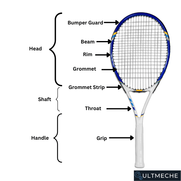
I was able to utilize all 3 in my project where I had to design and analyze a tennis racket.
I designed the tennis racket using various features such as extrusions, sweeps, revolves, and patterns.
From then on, I had to properly constrain all of the pieces of the tennis racket together:
- Handle
- Shaft
- Head
- Rim
- Beam
- Grommet
- Bumper
- Grip
As a bonus, I modeled an assembly with a tennis ball and performed a Finite Element Analysis (FEA) to show how the force distributes from the grommet to the rim. The results showed very concentrated stresses throughout the radius of the rim, which is very representative of how a tennis racket behaves.
What mechanical systems have you designed in CAD software?
I’ve designed mechanical systems such as power plant components – pumps, compressors, turbines, and condensers as well as aircraft and spacecraft for military and national security applications.
Tell me how you would model this fastener in CAD software.
You may get asked about how you would model certain features in CAD as a means to verify that you know how to do CAD in an interview.
At other times, employers may even quiz or test you on your knowledge of CAD.
This consists of you using CAD during the interview to model something.
Expect it to be something easy such as a bearing or a fastener.
Explain what the Carnot Power Cycle is.
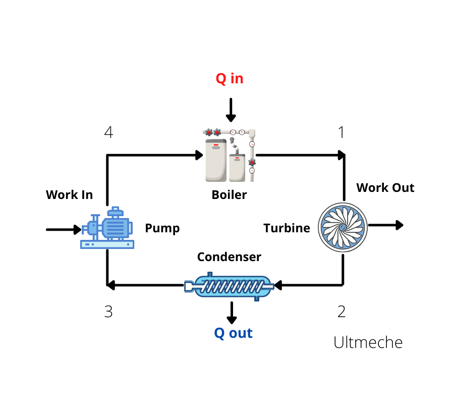
The Carnot Power Cycle is a 4 cycle process in which:
- 3-4, water gets pumped (Isentropic Compression)
- 4-1, the water that is pumped gets heated by the boiler (Isobaric Heat Addition)
- 1-2, the water that gets heated becomes a steam and the steam generates work through movement of turbine (Isentropic Expansion)
- 2-3, condense steam back into liquid (Isobaric Heat Rejection)
Ultimately, the goal of the cycle is to get work output from the turbine.
A simple way to calculate the efficiency of the system would be what we get over what we put in.
Efficiency = (Work Out) / (Work In + Q In)
What are the three laws of thermodynamics?
1st Law of Thermodynamics
Conservation of energy – energy cannot be created or destroyed, only converted.
2nd Law of Thermodynamics
Entropy in a given system must always increase.
(Practically speaking, this makes sense because as processes go on and on, they will get more disorganized – particles, friction, losses, etc.)
3rd Law of Thermodynamics
The entropy of a system approaches an absolute value as the temperature approaches zero.
The significance of this meaning that the entropy is an absolute value, which is one that can be calculated.
From this calculation, design parameters can be considered for thermodynamics systems.
Explain what conservation of energy is in a mechanical system.
Conservation of energy is defined by:

What are some real-life examples of losses in a mechanical system?
Real life examples of losses in a mechanical example are:
- Friction
- Head-loss
- Resistance
- Drag
Note that in engineering courses, in your calculations, you typically neglect losses for simplicity of calculations. In reality, we just have to deal with these losses and adjust for our results accordingly.
What are the three forms of heat transfer?
Conduction
Conduction is a form of heat transfer where heat is transferred directly upon contact.
Convection
Convection is the form of heat transfer through the utilization of fluids such as air to transfer heat from one medium to another.
Radiation
Radiation is the form of heat transfer that is emitted by photons of electromagnetic waves.
What is the functionality of a heat exchanger?
A heat exchanger is a mechanical system that transfers heat from a source and a working fluid.
Heat exchangers are used for cooling or heating purposes for fluids involved in mechanical systems.
Some practical examples of heat exchangers are water heaters or HVAC systems.
Can you explain what GD&T is?
GD&T refers to Geometric Dimensioning and Tolerancing.
GD&T defines a set of standards and principles used in manufacturing to make parts and assemblies produceable.
In CAD, we model everything in perfect dimensions, but in reality this is not the case.
The dimensions will vary from how we design something to how something comes out.
As a result, GD&T define these standards so we can fit parts together while taking into consideration the real life variance.
What is tolerance stack up analysis?
Tolerance stack up analysis is an exercise used in the mechanical engineering industry to determine whether parts or assemblies can fit due to variances in their geometry.
It is impossible for a parts in an assembly to be perfect, so to deal with this, we perform Tolerance Stack up analysis.
I’d like to highlight a specific situation where I had to perform tolerance stack up analysis on members of a beam.
I calculated how the parts would fit in a least material condition (LMC) and a maximum material condition (MMC) and verified that the structural members were able to go together.
This was for a mission critical fixture that we needed to get some key data for the customer.
Tell me what a basic dimension is.
A basic dimension is a theoretically perfect dimension.
Basic dimensions are represented with a box call out on the dimension.
Additionally, because they are theoretically perfect, basic dimensions need to have tolerances called out.
What does a true position call out mean?
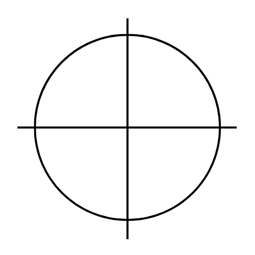
A true position defines the variance between the theoretical perfect position and the actual perfect position of a feature in a part.
Holes very commonly use a true position GD&T call out.
It is theoretically impossible to machine a hole on the EXACT location that is called out in a drawing.
True position is expressed usually in a diameter.
For a hole, the physical representation of a true position call out shows how much away the diameter of the actual hole can be drilled away from the theoretical perfect hole.
What is a flatness call out on a surface?
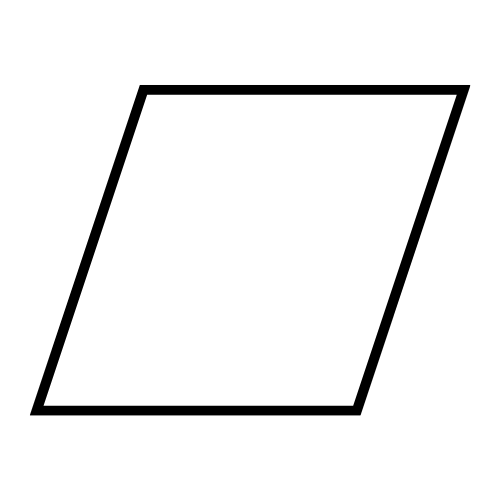
Flatness defines how flat a surface needs to be.
This is important to note because an example of where this is critical is when there is need for two contacting surfaces in a joint.
In some mechanical applications, we need to maximize contact area to utilize mechanical advantages like compressive stresses, clamping, gripping, etc.
To maximize this, we’d need as flat of a surface as we could get.
We use flatness call outs in leveling applications also.
What is a perpendicularity call out on a surface?
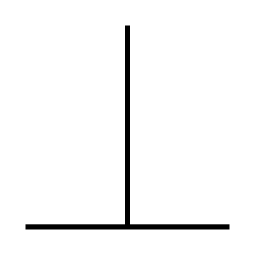
Perpendicularity defines how perpendicular a surface needs to be relative to a plane.
A perpendicularity call out requires the need to define the surface relative to an already existing feature.
It’s important for planes on surfaces to be perpendicular as needed to ensure that:
- Parts are aligned
- Parts will fit
- The welds for two parts that are perpendicular to each other are accurate
- The machining for two surfaces that are parallel to each other are accurate
In mechanical engineering, vertical alignment is a very important concept to understand and one of the keyways to achieve vertical alignment in a mechanical system is to correctly utilize a perpendicularity callout.
What is total indicated runout on a surface?
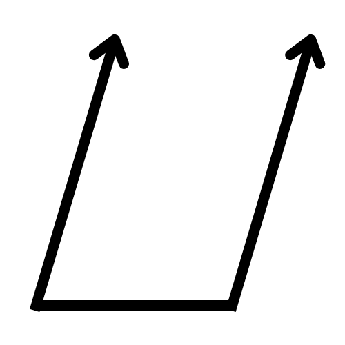
Total indicated runout on a surface defines the difference maximum and minimum values on a surface.
An example would be for a shaft.
To measure total indicated runout, you would get a dial indicator, set it up on a surface, zero it out, and rotate the shaft around the indicator.
The value you are essentially reading on the indicator is your runout.
Specific examples you would see total indicated runout would be:
- Register fits
- Closely aligning shafts
- Rotating machinery components such as shafts, bearings, anything with a bore diameter
What is cylindricity on a surface?
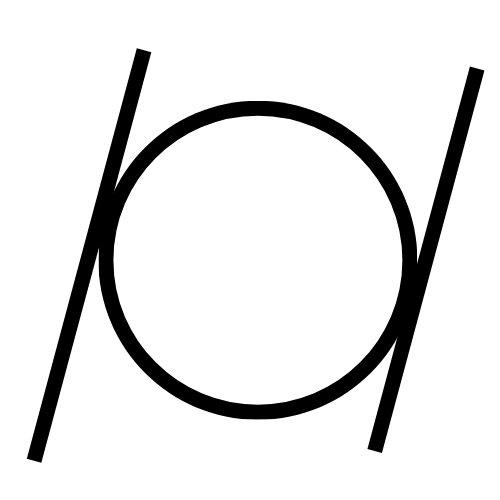
Cylindricity describes how representative an object is compared to a cylinder. It is a measurement that controls the overall surface of the respective cylindrical figure to verify both it’s roundness and straightness on an axis.
Cylindricity also represents the roundness and straightness of a component relative to an established datum/surface.
To measure cylindricity, we would take a dial indicator and run it on one surface.
Then once we have it zeroed out on that surface, we would then indicate the next surface.
Cylindricity is called out on applications such as hubs for couplings.
What is concentricity regarding GD&T?

Concentricity is the value in which the axis of two circular surfaces will lie within each other.
In mechanical systems such as couplings, it is important for surfaces to be concentric with each other.
This will ensure accuracy and axial alignment between the circular hub components.
Concentricity will be represented by a diameter and that diameter defines the largest value in which the axis can deviate from each other.
What is the difference between total indicated runout and cylindricity?
Concentricity defines how far away the axis of two circular surfaces can be.
Total Indicated Runout indicates the maximum difference for a given circular surface.
Total Indicated Runout is a much more applicable use and is a good call out to utilize for precision aligned components.
In a real life application, would you prefer working with looser tolerances or tighter tolerances, and why?
In real life, we prefer working with looser tolerances from a more economical standpoint.
Unfortunately, there are applications and industries in which higher tolerances are required, and as a result make the part produced more costly.
I find it important to apply loose tolerances as much as possible to make the part easier to product and assemble. This also explains the importance of using principles such as Design for Assembly (DFA) and Design for Manufacture (DFM).
In design reviews, we are required to showcase that the parts we design will fit and economically justifiable for what we’re doing.
What are some industries in which we may see tight tolerances?
In industries in which precisely manufactured components are required, we will see tight tolerances.
Some applications that require tighter tolerances are:
- Spacecraft components
- Aircraft components
- Pressure vessels
- Tightly clearance shafts
What are some industries in which we may see looser tolerances?
In applications that are not as precise in mechanical engineering, we can specify looser tolerances to be more economical.
Some applications are:
- Tooling Fixtures
- Loosely clearances shafts
- Hole clearances in Oil & Gas
Tell me about a difference between aluminum and steel.
The main difference between aluminum and steel are their material properties.
Aluminum has a high strength to weight ratio.
Steel has a lower strength to weight ratio and is much more denser.
We choose different materials based on their mechanical application.
Why would it be advantageous to use aluminum in a mechanical system?
Aluminum has a very high strength to weight ratio and as a result, is very easy to deal with and makes great tooling fixtures.
Aluminum parts are very easy to handle and lightweight.
The drawback is that although the material is light weight, is generally not as strong compared to steel.
Quick mechanical fixes can be made with aluminum adapters such as jig plates and supports.
Why would it be advantageous to use steel in a mechanical system?
Steel has relatively high strength and hardness properties that we want for given mechanical engineering applications.
Steel also provides corrosion resistance and can withstand certain extreme environments, which make steel a good choice to utilize.
What is heat treatment of a material?
Heat treatment involves the utilization of heating or cooling to achieve material properties such as hardness or softness of a material.
In practice, heat treatment of a material is usually done after rough machining and prior to final machining.
It has been seen that heat treatment after final machining causes parts to “warp”.
What does it mean if steel is annealed?
Metal is annealed to allow it to cool down slowly at a specified rate to remove internal stresses in the material and making it tougher.
Reducing the temperature at a specified rate removes grain impurities, increases metal ductility, and reduces hardness.
Depending on the material properties you want for the application you are using it for, you will want a material more brittle vs ductile or harder vs. not as hard.
Tell us about a time you have improved a process or feature on a product.
As a product design engineer for vertical turbine pumps, I was responsible for releasing bills of materials (BOMs).
The process of filling out those BOMs was manual – I would go into the file archive and select which specific components to use.
This was very inefficient to do, so as a result, I suggested to automate this process given inputs such as shaft diameter and hydraulic.
Given the specific hydraulic and shaft diameter, the associated components would be known such as bearings, wear rings, casings, impellers, and pretty much everything could be determined.
Along with these inputs, an envelope dimension can be provided to give the customer an understanding of the part.
A process I implemented was a configurable BOM within the pump configuration software we use.
As a result, this speeded up the process of bills of materials by 80%.
Tell us about your greatest technical challenge.
My greatest technical challenge involved being both the responsible design and test engineer for the static testing of an article.
The static testing involved design of a complex feature with tightly toleranced mandatory inspection points and complex geometry to work with.
I had to utilize every technical skill that I had to successfully carry out this project.
Skills from CAD modeling, to stress calculations, to tolerance stack up analysis to make sure everything fit.
There was variance in dimensions across the board, laterally and axially.
It was very challenging to meet the requirements, but they were met and I successfully contributed to validate test results of a mission critical component.
What is model-based systems engineering?
Model-based systems engineering is a newer practice in engineering where the model acts as the authority.
Up until recent, most designs were drawing based.
However, many companies are going through a “digital transformation” phase where they are leveraging the technology such as cloud computing, machine learning, and artificial intelligence.
As a result, companies are looking to go digital where they can and the building of various cloud libraries start commencing.
What skills do a mechanical engineer need to be successful?
A successful mechanical engineer is one who is very mechanically inclined.
They understand engineering principles and are able to apply them on the feet to understand situations and provide recommendations and solutions.
A successful mechanical engineer is also not afraid to say when they don’t know the solution, but they will find the answer when presented with an issue.
A successful mechanical engineer is also one who is not afraid to speak up, ask questions, or challenge authority.
I’d like to highlight a situation where I demonstrated some of those concepts by XXXX.
(And use a story pertaining to your individual success)
Do you have any design questions for us?
Some design questions you can ask in a mechanical engineering interview are
- What is your long term outlook for mechanical engineering in XXX industry?
- What are some of the biggest day to day challenges in designing?
- Did I say anything in the interview that hurt my chances of getting the job, and if so, is there any way I can address it?
- What’s your favorite part about mechanical engineering?
- Upon hiring, how can I ensure that I have the resources I need to become successful as a mechanical engineer?
More specific mechanical engineering interview questions
Check out the following for more detailed mechanical engineering interview questions:
- Thermodynamics Interview Questions
- Strength of Materials Interview Questions – Top 23
- Machine Design Interview Questions – Top 13
- Mechatronics Interview Questions – Top 15
- Structural Engineering Interview Questions
About the author

Kazuyoshi Fujimoto, PE
Founder | Engineering Career Coach | Principal Mechanical Engineer
Kazu oversees all of ultmeche’s engineering services. He provides consulting such as resume reviews, rewrites, mock interviews, and all services career related. Additionally, Kazu performs consulting work regarding Oil & Gas, Automotive, and Aerospace & Defense. Kazu is licensed as a professional engineer in the state of California and has 9+ years of experience in Oil & Gas, Automotive, and Aerospace & Defense.

2 thoughts on “60 Mechanical Engineer Interview Questions”