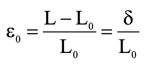
The strain formula is ε = δ / L
Represented by the following variables:
- ε = strain
- δ = material displacement
- L = Initial length of material
If we take into a account an axially loaded beam shown in the figure, where the small line element AB = ∆x suffers a deformation to become the element A’B’
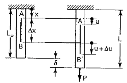
The point A has been displaced by an amount u, and B by u + ∆u
It is shown that the length of the line element A’B’ is ∆x + ∆u .
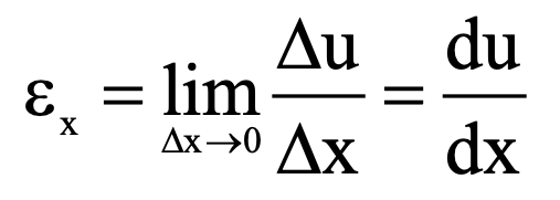
The strain in the beam at the point A is defined as the change in length per unit length as ∆x → 0 and is given by Eq
If the deformation is distributed uniformly over the original length, the normal strain may be expressed in the form given in Eq
Check out: What is Strain in Engineering?
2D Displacement and Strain Formulas
For the 2D strain field, let’s take into account a deformation that is independent of one Cartesian coordinate, say z.
Let a point P with Coordinates (X, Y) in the undeformed state be displaced to the point P’ with coordinates (x, y), as a result of the deformation of the body.
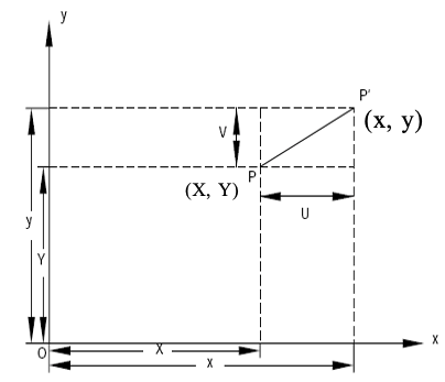
The displacement of the point P is a vector with Cartesian components (U, V), such as:
U = x – X and V = y – Y
As a result, it will be assumed that the displacement components are continuous and twice differentiable functions of X, Y or x, y.
Let’s take into account a small rectangular element PQRS in the undeformed state, with sides (dX, dY) parallel to the coordinate axes.
Then we’re going to let points P, Q, R and S move to P’, Q’, R’ and S’, respectively, after deformation
Recall from the previous case:
U = x – X, V = y – Y
This will give us the following set of equations:
x = X + U and y = Y + V
Then by using a Taylor Series expansion method to uncover the differentials:
dx = dX + dU = (approximate) dX + (∂U/ ∂X)dX
dy = dV = (approximate) (∂V/ ∂X)dX
We will then get, as a result of the Taylor series expansion:
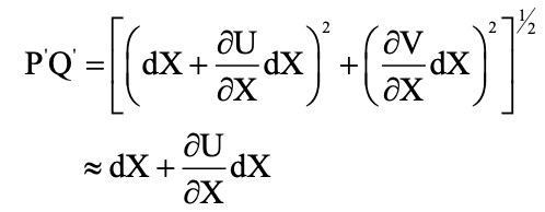
In which where we have neglected the squares and products of (∂U/ ∂X) and (∂V/ ∂X).
Normal Strains
As a result, the increase in length per unit length of the line PQ, denoted by εx , is given by εx = ∂U/ ∂X

The increase in length of line PS will be given by
εy = ∂V/ ∂Y
The quantities εx and εy are known as the normal strains
Let’s take into account the 2D strain displacement plane shown below
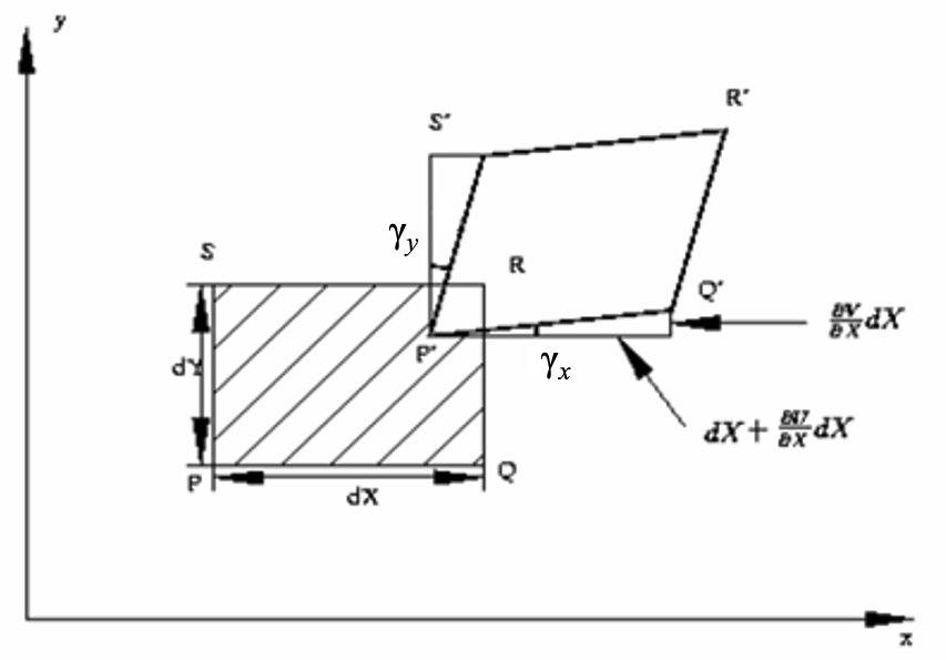
If γx denotes the angle that P’Q’ make with the x-axis, from the figure we will have:
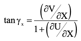
Assuming that the angle γx (measured in radians) is small and neglecting small quantities of the second order and higher orders in (∂U/ ∂X) and (∂V/ ∂X), we have the following equations for the strain displacement angles:

Shear Strain Formula
Let γxy denote the change in the angle between the two lines PQ and PS which are parallel to the x- and y-axes, respectively, before deformation
Then we will get the following equation:

The above equation relates the shearing strain γxy to the displacement gradients
The symbol εxy is also used to define the shearing strain.
The strain-displacement relations are the main results of the analysis.
They’ve been derived under the assumption that the displacement derivatives or gradients are very small compared to unity.
In deriving the earlier equations, the products and squares of the displacement gradients have been assumed to be negligible in comparison with the gradients themselves and the distinction between X, Y, Z, U, V, W and x ,y, z, u, v, w have been ignored.
These two assumptions form the foundation of the linear theory of elasticity.
3D Strain Displacement Relations
In the general case of three-dimensional deformation, there are three normal strains, εx, εy, εz, and three shearing strains, γxy, γyz, and γzx.
They are related to the displacement components U, V, and W as a result of the equations

The change in an angle is the same if it occurs between the x and y directions or the y and x directions.
So as a result, γxy = γyx for the shearing strains
Similarly, the components for the shearing strain are related in the other directions:
γyz = γzy and γzx = γxz
The symmetry of the shearing strains is also obvious from the strain-displacement relations
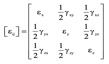
Just as the state of stress at a point is described by a nine-term array, similarly the state of strain can also be described by nine term array
Hooke’s Law Stress and Strain Formula
In the figure below, it is shown that the linear portion of the diagram stress is directly proportional to strain
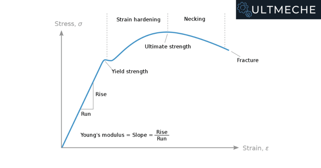
If we are taking into account stresses in the “x-axis”
We will get for the Hooke’s law relationship

Hooke’s law is valid only if the other normal components of stress, namely, σy and σz are absent.
Young’s Modulus
The constant E is called the modulus of elasticity, or Young’s modulus.
E is the slope of the stress-strain diagram in the linearly elastic region.
Shear Modulus
Similarly for two-dimensional pure shear loading in the linear elastic range it has been found experimentally that stress and strain are also related linearly in the form:

The constant G is called the shear modulus, or modulus of rigidity of the solid.
Check out: What is Stress in Engineering?
Poisson’s Ratio
In the linearly elastic region of the stress strain curve, let’s take a look at the lateral strains.
For the lateral strains in the y and z direction, they will be linearly related to the strain component in the x direction.
This relationship will be defined by a constant of proportionality, ν.
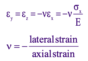
The constant ν is known as the Poisson’s ratio of the solid.
For most metals ν varies between 0.25 to 0.35.
In extreme cases its values range from a low of 0.1 (for concretes) to a high of 0.5 (for rubber)
Closing Thoughts on Strain Formulas
Strain is also a complicated subject matter in a strength of materials class.
The knowledge and application of strain to determining whether or not mechanical systems will operate is crucial to mechanical design.
In real world applications, strain will be taken as a measurement and compared to material specimen testing reports for product qualification testing.
About the author

Kazuyoshi Fujimoto, PE
Founder | Engineering Career Coach | Principal Mechanical Engineer
Kazu oversees all of ultmeche’s engineering services. He provides consulting such as resume reviews, rewrites, mock interviews, and all services career related. Additionally, Kazu performs consulting work regarding Oil & Gas, Automotive, and Aerospace & Defense. Kazu is licensed as a professional engineer in the state of California and has 9+ years of experience in Oil & Gas, Automotive, and Aerospace & Defense.

1 thought on “Strain Formula”